Using a Resistance Sealing Nail Welding Machine well means controlling the details that are easy to overlook: electrode condition, clamping pressure, current, and weld time. A nail seated slightly off-center can leave an uneven seal. A worn electrode can change the result, even when the settings remain unchanged. Small variations matter.
Automation is expanding, but market-wide figures should not be mistaken for data about this specific machine. The International Federation of Robotics reported 4,281,585 industrial robots operating worldwide in 2023, a 10% increase from 2022, in its World Robotics 2024 report. That figure reflects industrial robotics broadly; it does not measure resistance sealing nail welding equipment. Still, it highlights why repeatable, well-checked production processes matter.
Start with the machine maker’s operating instructions and a test piece. Inspect the electrode faces. Confirm the workpiece sits flat. Then adjust one parameter at a time and record the results. Check the seal visually and, where appropriate, with a consistent test method. Do not assume that a setting that worked on one material will suit another.
A note on sourcing: I could not verify a published quotation from a named specialist specifically about this machine, so I will not invent one. A useful shop-floor reminder is simple: “Test the setup before the run.” The habit is practical, though no test can replace the machine’s documented specifications or trained operator judgment.

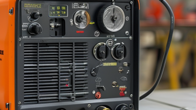
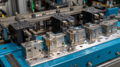
A resistance sealing nail welding machine typically includes a power unit, welding head, electrodes, pressure mechanism, controls, and a workholding fixture. The fixture keeps the parts aligned while the head presses the nail and workpiece together. On some machines, a feed guide positions each nail; its design varies by model. Look for clean electrode faces and secure cables before setup. Small details matter.
The welding cycle combines pressure and electrical current. The electrodes clamp the joint, then current passes through the contact area, generating heat that forms the weld. The controller sets variables such as current, force, and weld time; follow the machine’s manual rather than guessing values. After the pulse, pressure may remain briefly while the joint cools. A dull mark or loose nail can signal poor contact, misalignment, or worn electrodes, but appearance alone cannot confirm weld strength. Use the specified inspection method and protective equipment. It is tempting to blame the settings first. Check the fixture, material fit, and electrode condition too; I would not treat one successful weld as proof that the setup is consistent.
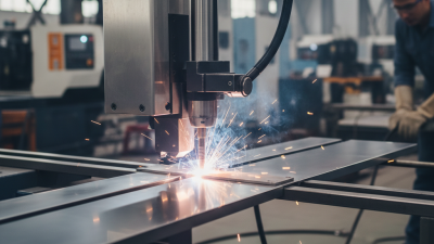
Illustrative stage durations show how the machine’s electrodes position and clamp the workpieces, apply a brief current pulse, hold pressure, and release. Actual cycle times depend on the machine, materials, and setup; follow the equipment manufacturer’s specifications.
Before switching on a resistance sealing nail welding machine, inspect the power lead, grounding, guards, foot pedal, and emergency stop. Check that electrodes are clean, aligned, and firmly seated. Wear safety glasses and close-fitting work gloves; keep sleeves and hair away from moving parts. Small checks matter. Arrange local extraction if coatings or contaminants may produce fumes. The ILO’s 2023 report, A Call for Safer and Healthier Working Environments, estimated 2.93 million work-related deaths worldwide in 2019. That figure covers all industries, not welding alone, but it underscores why routine checks should never become a rushed ritual.
Prepare the workpieces on a stable bench. Remove oil, loose rust, and burrs from the contact area, while checking coatings before disturbing them. Match the nail position to the fixture marks, then clamp the parts so they cannot shift under electrode pressure. Keep hands clear. Confirm the specified force and weld time from the machine instructions, rather than guessing from appearance. Run a sample on matching scrap and inspect the joint for movement, uneven marks, or incomplete bonding. I still find it easy to overlook a slightly tilted nail when production gets busy; a quick alignment check is worth the pause.
| Stage | Check or Preparation | Action | Acceptance Criteria | When to Check |
|---|---|---|---|---|
| Operator readiness | Training and work instructions | Confirm the operator is trained for the machine and the approved welding procedure is available. | The operator understands the controls, hazards, and approved setup for the specific materials and nail type. | Before operation and when the procedure changes |
| Personal protection | Eye, hand, and clothing protection | Wear safety glasses with side protection and other PPE required by the site risk assessment. Secure loose clothing and hair. | PPE is suitable, undamaged, and worn before loading or welding. | Before each shift |
| Work area | Fire and access hazards | Remove combustible debris from the work area, keep access clear, and follow site fire-watch requirements where applicable. | The area is orderly, adequately lit, and free of unnecessary combustible materials near the weld zone. | Before starting and after moving the machine |
| Machine safety devices | Guards, interlocks, and emergency stop | Visually inspect guards and cables, and verify safety devices using the approved start-up check. Do not bypass interlocks. | Guards are in place, cables show no visible damage, and safety devices function as intended. | Before each shift |
| Electrical and utility supply | Power, grounding, and connected services | Check the supply against the machine’s rated requirements. Confirm protective grounding and inspect any required air or cooling connections. | Connections are secure, within the specified operating range, and free of visible leaks or damage. | Before start-up |
| Electrode and tooling condition | Electrode faces, holders, and alignment | Inspect for contamination, wear, looseness, or misalignment. Clean or replace tooling according to the machine procedure, with power isolated when required. | Contact faces are clean and correctly aligned; tooling is secure and serviceable. | Before production and whenever weld quality changes |
| Workpiece compatibility | Base material, thickness, and nail specification | Verify that the workpiece and nail materials, dimensions, and coating are covered by the approved welding procedure. | Materials and joint configuration match the procedure; uncertain combinations are reviewed before welding. | For each new job or material lot |
| Surface preparation | Weld contact area | Remove oil, moisture, loose scale, rust, paint, and other contaminants from the specified contact area using an approved method. | The contact area is clean and dry, with no residue that could interfere with electrical contact or the weld. | Before loading each workpiece |
| Positioning and clamping | Workpiece support and nail location | Place the workpiece on a stable support, locate the nail at the specified position, and secure the part without obstructing the electrodes or guards. | The workpiece cannot shift during the weld cycle and the electrode can make the intended contact. | For every workpiece |
| Weld setup | Current, time, force, and sequence | Select settings only from the qualified procedure or validated machine setup for the specific joint. Do not substitute unverified values. | Settings match the approved procedure and the machine displays no active fault. | At setup and after any parameter change |
| Trial weld and inspection | First-off sample | Make a trial weld on a representative sample when required, then inspect it using the acceptance method defined for the job. | The sample meets the specified visual and mechanical acceptance criteria before production continues. | At the start of a job and after setup changes |
| Production monitoring | Weld consistency and machine condition | Monitor the weld cycle and check samples at the frequency required by the quality plan. Stop if the machine behaves abnormally or welds become inconsistent. | Welds continue to meet the defined acceptance criteria, with no unresolved machine fault. | Throughout production |
| Adjustment and maintenance | Electrical or mechanical intervention | Stop the machine and follow the site isolation and lockout procedure before servicing, clearing a jam, or reaching into a hazardous area. | The machine is isolated and verified safe before intervention; only authorized personnel perform service work. | Whenever intervention is needed |
Start with the workpiece material, thickness, and electrode condition; these determine a sensible starting range for current, weld time, and electrode force. Follow the machine’s operating guidance rather than copying settings from a different setup. Clean the contact area so oil, scale, or loose debris does not disrupt the weld. Small changes matter.
Make a test weld on matching scrap. Increase or reduce one setting at a time, then check for consistent attachment, excessive indentation, discoloration, or metal expulsion. A weak joint may need adjustment, but raising current alone can overheat the sheet. Record the settings that produce a stable result, including the electrode condition and material thickness. I still treat those notes as a starting point, not a guarantee; worn electrodes and small material changes can shift the outcome.
Position the sealing nail square to the work surface and align its base with the marked spot. Use a fixture or stop when repeatable placement matters. Keep the nail from tilting as the electrodes make contact, and confirm that the clamping force holds it without shifting. Keep it steady. Before production, inspect a sample weld and verify the nail’s alignment and attachment. If the fit looks uneven, pause and check the fixture, contact surfaces, and settings before continuing.
Before starting the welding cycle, confirm that the nail and sealing surface are aligned and firmly held. Check that the electrode faces are clean, undamaged, and seated squarely. Use the validated settings for the material and thickness; do not guess from appearance alone. Keep hands clear, then start the cycle and watch its full sequence: clamping, current application, hold, and release. Listen for changes in the machine’s normal sound. If the display provides current, time, or force data, compare each reading with the approved process range. Pause production if an alarm appears or a reading drifts. Small changes matter.
Inspect the joint after the part has cooled enough to handle safely. Look for a consistent weld impression around the nail, secure contact, and no visible gaps, excessive spatter, or burn-through. A neat surface mark is not proof of a sound joint; use the specified sample test when required. Record the settings and inspection results so another operator can trace the run. If a joint looks questionable, isolate it and check alignment, electrode condition, and process records before adjusting anything. Even experienced operators can miss a subtle defect, especially when the part is warm or the lighting is poor.
Inspect each weld under bright, angled light. Look for uniform seating, a consistent imprint, no cracks, and no metal splash around the seal. Look closely. Visual checks can miss weak internal fusion, so test sample parts with an appropriate peel or cross-section method. Record weld current, time, electrode force, and results together; a neat surface alone does not prove a sound joint. AWS D8.9M and ISO 18278-2 describe test approaches for assessing resistance-weld performance and weldability.
Check electrode faces for mushrooming, pitting, and residue. Clean or dress them to the machine maker’s specifications, then verify alignment, cooling flow, cables, and connections. Keep a dated log of settings and maintenance; small changes in electrode wear can shift weld results. McKinsey’s 2018 manufacturing analytics report estimates predictive maintenance can reduce equipment downtime by 30–50% and maintenance costs by 10–40%. Those figures cover industrial settings broadly, not this machine specifically. Treat them as potential, not a promise. And be honest: a maintenance log helps, but it cannot replace periodic destructive tests.